- 您现在的位置:买卖IC网 > Sheet目录340 > MAX16821CATI+T (Maxim Integrated)IC LED DRIVR HIGH BRIGHT 28-TQFN
�� �
�
 �
�High-Power� Synchronous� HBLED�
�Drivers� with� Rapid� Current� Pulsing�
�PCB� Layout�
�Use� the� following� guidelines� to� layout� the� LED� driver.�
�Selector� Guide�
�1)� Place� the� IN,� V� CC� ,� and� V� DD� bypass� capacitors�
�close� to� the� MAX16821A/MAX16821B/MAX16821C.�
�2)� Minimize� the� area� and� length� of� the� high-current�
�switching� loops.�
�3)� Place� the� necessary� Schottky� diodes� that� are� con-�
�nected� across� the� switching� MOSFETs� very� close� to�
�the� respective� MOSFET.�
�PART�
�MAX16821A�
�MAX16821B�
�MAX16821C�
�DIFFERENTIAL�
�SET� VALUE�
�(V� SENSE+� -� V� SENSE-� )�
�(V)�
�0.60�
�0.10�
�0.03�
�DIFFERENTIAL�
�AMP� GAIN�
�(V/V)�
�1�
�6�
�20�
�4)� Use� separate� ground� planes� on� different� layers� of�
�the� PCB� for� SGND� and� PGND.� Connect� both� of�
�these� planes� together� at� a� single� point� and� make�
�this� connection� under� the� exposed� pad� of� the�
�MAX16821A/MAX16821B/MAX16821C.�
�5)� Run� the� current-sense� lines� CSP� and� CSN� very�
�close� to� each� other� to� minimize� the� loop� area.� Run�
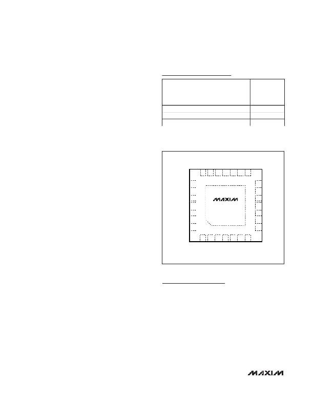
�TOP� VIEW�
�Pin� Configuration�
�the� sense� lines� SENSE+� and� SENSE-� close� to� each�
�other.� Do� not� cross� these� critical� signal� lines� with�
�21�
�20�
�19�
�18�
�17�
�16�
�15�
�power� circuitry.� Sense� the� current� right� at� the� pads�
�of� the� current-sense� resistors.� The� current-sense�
�signal� has� a� maximum� amplitude� of� 27.5mV.� To� pre-�
�vent� contamination� of� this� signal� from� high� dv/dt�
�and� high� di/dt� components� and� traces,� use� a�
�ground� plane� layer� to� separate� the� power� traces�
�from� this� signal� trace.�
�6)� Place� the� bank� of� output� capacitors� close� to� the� load.�
�7)� Distribute� the� power� components� evenly� across� the�
�SGND� 22�
�SENSE-� 23�
�SENSE+� 24�
�SGND� 25�
�IN� 26�
�V� CC� 27�
�V� DD� 28�
�+�
�MAX16821A�
�MAX16821B�
�MAX16821C�
�*EP�
�14�
�13�
�12�
�11�
�10�
�9�
�8�
�I.C.�
�OUTV�
�RT/SYNC�
�EN�
�MODE�
�CLKOUT�
�SGND�
�board� for� proper� heat� dissipation.�
�8)� Provide� enough� copper� area� at� and� around� the�
�1�
�2�
�3�
�4�
�5�
�6�
�7�
�switching� MOSFETs,� inductor,� and� sense� resistors�
�to� aid� in� thermal� dissipation.�
�9)� Use� 2oz� or� thicker� copper� to� keep� trace� inductances�
�and� resistances� to� a� minimum.� Thicker� copper� con-�
�ducts� heat� more� effectively,� thereby� reducing� thermal�
�impedance.� Thin� copper� PCBs� compromise� efficiency�
�in� applications� involving� high� currents.�
�*EP� =� EXPOSED� PAD.�
�PROCESS:� BiCMOS�
�TQFN�
�Chip� Information�
�22�
�______________________________________________________________________________________�
�发布紧急采购,3分钟左右您将得到回复。
相关PDF资料
MAX16822AASA/V+
IC LED DRIVER HIGH BRIGHT 8SOIC
MAX16826ATJ+C24
IC LED DVR HB PROGR 32-HQFN
MAX16835ATE+T
IC LED DRIVR HIGH BRIGHT 16-TQFN
MAX16838AUP+
IC LED DRIVR HIGH BRIGHT 20TSSOP
MAX1698EUB
IC LED DRVR WT/CLR BCKLGT 10MSOP
MAX17014EVKIT+
KIT EVAL FOR MAX17014
MAX17061AETI+T
IC LED DRVR WHITE BCKLGT 28-TQFN
MAX17061ETI+T
IC LED DRVR WHITE BCKLGT 28-TQFN
相关代理商/技术参数
MAX16821EVKIT+
制造商:Maxim Integrated Products 功能描述:HIGH-POWER SYNCHRONOUS HBLED DRIVER - Boxed Product (Development Kits)
MAX16822AASA/V+
功能描述:LED照明驱动器 2MHz HB w/MOSFET & HSide Crnt Sense RoHS:否 制造商:STMicroelectronics 输入电压:11.5 V to 23 V 工作频率: 最大电源电流:1.7 mA 输出电流: 最大工作温度: 安装风格:SMD/SMT 封装 / 箱体:SO-16N
MAX16822AASA/V+T
功能描述:LED照明驱动器 2MHz HB w/MOSFET & HSide Crnt Sense RoHS:否 制造商:STMicroelectronics 输入电压:11.5 V to 23 V 工作频率: 最大电源电流:1.7 mA 输出电流: 最大工作温度: 安装风格:SMD/SMT 封装 / 箱体:SO-16N
MAX16822AASA+
功能描述:LED照明驱动器 2MHz HB w/MOSFET & HSide Crnt Sense RoHS:否 制造商:STMicroelectronics 输入电压:11.5 V to 23 V 工作频率: 最大电源电流:1.7 mA 输出电流: 最大工作温度: 安装风格:SMD/SMT 封装 / 箱体:SO-16N
MAX16822AASA+T
功能描述:LED照明驱动器 2MHz HB w/MOSFET & HSide Crnt Sense RoHS:否 制造商:STMicroelectronics 输入电压:11.5 V to 23 V 工作频率: 最大电源电流:1.7 mA 输出电流: 最大工作温度: 安装风格:SMD/SMT 封装 / 箱体:SO-16N
MAX16822BASA+
功能描述:LED照明驱动器 2MHz HB w/MOSFET & HSide Crnt Sense RoHS:否 制造商:STMicroelectronics 输入电压:11.5 V to 23 V 工作频率: 最大电源电流:1.7 mA 输出电流: 最大工作温度: 安装风格:SMD/SMT 封装 / 箱体:SO-16N
MAX16822BASA+T
功能描述:LED照明驱动器 2MHz HB w/MOSFET & HSide Crnt Sense RoHS:否 制造商:STMicroelectronics 输入电压:11.5 V to 23 V 工作频率: 最大电源电流:1.7 mA 输出电流: 最大工作温度: 安装风格:SMD/SMT 封装 / 箱体:SO-16N
MAX16822BEVKIT+
功能描述:LED 照明开发工具 MAX16822B Eval Kit RoHS:否 制造商:Fairchild Semiconductor 产品:Evaluation Kits 用于:FL7732 核心: 电源电压:120V 系列: 封装: